Reducing cable congestion in constrained spaces is an important factor in designing fiber systems for data centers and large enterprise equipment rooms and data centers. Network designers turn to multi-fiber MTP/MPO cabling to overcome this challenge. Ensuring correct polarity across the system becomes more complex with higher data rates.
TIA-568 standard has approved 3 methods for configuring system polarity in multi-fiber arrays – Methods A, B and C.
Before getting into the methods in detail, let us take a look at the basic components of an MPO system.
MPO System Components
MPO Connector:
MPO/MTP connectors utilize a pin and socket feature to ensure proper alignment of the connectors when mating two connectors.

MPO connectors have an extrusion, called a “key”, on one side of the MPO/MTP connector to ensure proper polarity when connectors are mated. When discussing polarity, you will hear the terms “key up” and “key down”; these terms describe the orientation of the connector. “Key up” means that the extrusion on the connector is facing up. “Key down” means that the extrusion on the connector is facing down. Each of the fiber holes in the connector is numbered in sequence from left to right and is referred as fiber position, or P1, P2, etc. A white dot is marked on one side of the connector to denote where the position 1 is.
MPO Adapter:
MPO (male) connectors are mated to MPO(female) connectors using a MPO adapter., There are 2 types of MPO adapters: Type A—key-up to key-down Type B—key-up to key-up
MPO Cables:
MPO trunk cables which are available in 12, 24, 32, 48 etc. fibers with MPO connectors (male/female) on both ends serve as permanent links connecting the MPO modules to each other. There are 3 types of trunk cables, Type A, B and C.
MPO Cassette: Modular MPO cassette is enclosed unit that usually contains 12 or 24-fiber factory terminated fan-outs inside. It enables the user to take the fibers brought by a trunk cable and distribute them to a duplex cable with a MPO connector to the more common LC or SC interface.
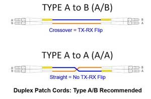
Different polarity methods use different types of MTP trunk cables. However, all the methods employ duplex patch cables to achieve the fiber circuit. The TIA standard also defines two types of duplex fiber patch cables terminated with LC or SC connectors to complete an end-to-end fiber duplex connection:
A-to-A type patch cable—a cross version and A-to-B type patch cable—a straight-through version.
METHOD A: Polarity flip in A‐to‐A patch cord
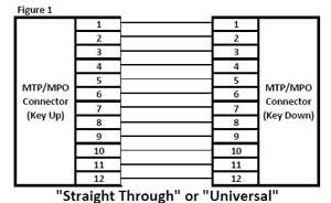
For method A, the transmit‐receive flip must happen in the patch cords, and the trunk cable is a straight through transmission, with the key up on one end, and the key down on the opposite end. This means that the fiber in Position 1 of the connector on the left will arrive at Position 1 at the other connector.
A type-A trunk cable connects a MPO module on each side of the link. In Method A, two types of patch cords are used to correct the polarity. The patch cable on one end is standard duplex A-to-B type, while on the other end a duplex A-to-A type patch cable is employed. Type A MPO adapters all have a key up on one side and the mating connector key down on the other side.
METHOD B: Polarity flip in adapter/cassette
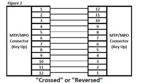
Type B trunk cable uses key up connector on both ends. This type of array mating results in an inversion, which means the fiber positions are reversed at each end. The fiber that is at position 1 in one connector end is in position twelve at the opposite end and the fiber that is in position 12 at the originating end is in position 1 at the opposing end.
Connectivity method B employs standard A-to-B type duplex patch cables and type B key up to key up adapters on both ends.
METHOD C: Flip by pairs
Type C cable (pairs flipped cable) looks like Type A cable with one key up connector and one key down connector on each side. However, in Type C each adjacent pair of fibers at one end are flipped at the other end. For example, the fiber at position 1 on one end is shifted to position 2 at the other end of the cable. The fiber at position 2 at one end is shifted to position 1 at the opposite end etc.
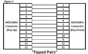
In this method, patch cords at both ends are the standard duplex A-to-B type. Note that for Method C polarity, Type A adapters should be used with Type C array cords.
Summary
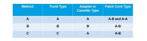
A simple way to look at these polarity methods is that Method A is the most straight forward but requires a different patch cord at one end. Method B uses the same patch cord at both ends, but the cassettes must be flipped over at one end so that the fiber that originated in position 1 is mapped to position 12. Method C is a variant of Method A, but with the cross-over implemented in the trunk cable instead of the patch cord. Both Method B and Method C have the advantage of using the same patch cords at both ends.
Here is a table with components used in each method:
GKoptic provides all 3 types of MTP and MPO trunk cables as well as fiber patch cords for datacomm and telecom applications. If you have any questions, please contact us at sales@gkoptic.com.